How to test stainless steel for corrosion resistance is not answered by one quick spray test. Stainless steel may look flawless under bright factory lighting, yet tiny pits can form beside a weld, under a fingerprint, or beneath a salt deposit. A reliable evaluation connects the alloy grade, surface finish, fabrication history, and service environment.
Mars G. Fontana, a respected corrosion engineering authority, wrote, “Corrosion is the deterioration of a material, usually a metal, by reaction with its environment.” That principle guides practical testing. Inspect the surface first, then record the steel grade and passivation condition. Clean and weigh specimens consistently. Expose them to chloride immersion, humidity, or salt spray under controlled conditions. ASTM G31 can support immersion testing, while ASTM B117 is commonly used for salt spray exposure. These methods reveal different weaknesses.
Measure mass loss, pit depth, rust staining, and changes around welds. Electrochemical tests can add faster information about pitting potential and passive-film stability. Test controls matter. Use identical specimen sizes, exposure times, temperatures, and solution concentrations. Otherwise, attractive data may hide poor comparisons.
No single test is perfect. Salt spray can exaggerate some environments, while short laboratory exposures may miss delayed pitting. Real service conditions deserve attention. A coastal railing, pharmaceutical vessel, and food-processing surface need different test plans. Even experienced teams sometimes overinterpret a clean appearance. The better approach combines standards, field knowledge, repeat specimens, and honest review of unexpected results. That is how testing becomes evidence, not merely reassurance.
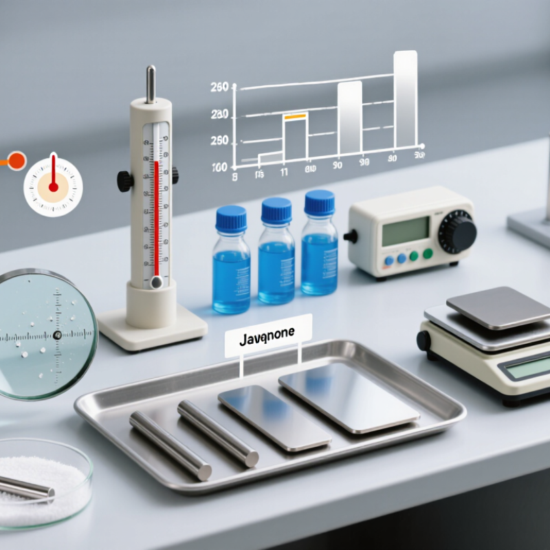
The purpose of stainless steel corrosion testing is not simply to produce a shiny pass or fail result. Testing helps determine how a steel grade, surface finish, and manufacturing process behave in a defined environment. Engineers may investigate pitting, crevice corrosion, staining, or general metal loss. These results support material selection and quality control.
Corrosion is an electrochemical process. Stainless steel normally protects itself with a thin passive oxide film. Chloride ions, acidic moisture, scratches, or contamination can damage this film. A test then measures how quickly corrosion begins and how severely it develops. Common approaches include immersion exposure, salt spray testing, and electrochemical polarization. Each method uses controlled temperature, solution chemistry, exposure time, and specimen preparation. Small details matter. Fingerprints can affect results.
Reliable testing requires calibrated instruments, clean equipment, repeat specimens, and complete records. Operators should inspect surfaces before and after exposure, measure pit depth when necessary, and compare results with a suitable standard. Testing only one sample is risky. A polished coupon may perform better than a production component with welds and sharp crevices. Laboratory exposure also cannot reproduce every outdoor or industrial condition. Visual ratings may vary between inspectors. That weakness deserves attention, not concealment. Good corrosion testing combines measurable data with practical knowledge of the component’s actual service environment.
Reliable corrosion testing begins with sample selection, not the test chamber. Cut coupons from production material, preserving rolling direction, welds, heat-affected zones, and surface finish. Record grade, thickness, heat number, preparation method, and cleaning procedure. A polished coupon may hide damage found on a brushed or welded surface. Include both conditions when service exposure is uncertain. Use at least three replicate samples where possible; one coupon can mislead.
Equipment must match the failure mechanism. ASTM G48 ferric chloride testing is useful for screening pitting and crevice corrosion resistance. ASTM G150 measures critical pitting temperature under controlled electrochemical conditions. For intergranular attack, ISO 3651-2 provides relevant practice. Use calibrated thermometers, reference electrodes, timers, and analytical balances. Check the chamber for contamination before testing. Small errors matter.
Test conditions should represent service, but accelerated testing needs discipline. Control chloride concentration, pH, temperature, dissolved oxygen, exposure time, and crevice geometry. A 5 °C temperature change can alter pitting behavior near a critical threshold. Record open-circuit potential and visually map pit size after exposure. NACE’s IMPACT study estimated global corrosion costs near US$2.5 trillion, or about 3.4% of global GDP, showing why defensible data matters. Still, laboratory severity is not field reality. I have seen clean coupons pass while rough weld zones failed. That uncomfortable gap deserves investigation.
Accurate corrosion testing begins with disciplined specimen preparation. Before cutting, record the stainless steel grade, heat number, thickness, and surface condition. These details connect the result to the material’s real history. Use clean tools that will not transfer carbon steel particles. A rushed cut can create heat tint, burrs, or residual stress. That error may look like poor corrosion resistance.
Cut specimens to consistent dimensions, then label them without touching the test area. Deburr the edges carefully, but do not round more surface than necessary. Preserve the production surface when it represents service conditions. For comparison tests, prepare a second set with a defined finish, such as a controlled abrasive sequence. Clean each piece with a suitable laboratory solvent, rinse with high-purity water, and dry with clean air. Handle specimens with gloves.
Masking must be uniform. Exposed area affects current density and corrosion measurements. Check every seal for gaps before immersion. Include replicate specimens and, when practical, an unexposed reference sample. Follow the selected ASTM or ISO procedure, including solution temperature, exposure time, and evaluation method. Record photographs before and after testing. Do not trust appearance alone. Small pits can hide beneath deposits or discoloration. I have seen inconsistent cleaning create misleading results. Preparation is not perfectly neutral, so review each step and question any result that conflicts with the material’s known behavior.
The chart shows representative midpoint values from commonly specified composition ranges for major stainless-steel grades. Before corrosion testing, specimens should be cut without overheating, cleaned to remove oils and residues, deburred, measured, and finished using a consistent abrasive procedure. Record the alloy grade, surface finish, dimensions, and exposed area so that mass loss or corrosion-rate results can be compared accurately.
Composition screening supports specimen identification but does not replace standardized exposure tests. Actual corrosion resistance also depends on surface condition, welding history, inclusions, environment, temperature, and test duration.
How to Test Stainless Steel for Corrosion Resistance?
Corrosion testing should begin with a defined service condition, not a convenient laboratory shortcut. The NACE IMPACT study estimated global corrosion costs at US$2.5 trillion, or 3.4% of global GDP, in 2013. Small testing errors can become expensive field failures. Record the steel grade, surface finish, heat treatment, and weld condition. Cut representative coupons, remove oils with a suitable solvent, and avoid touching cleaned surfaces with bare hands. Dry them completely. Fingerprints can create misleading corrosion sites.
For general atmospheric exposure, place prepared specimens in a salt spray chamber following ISO 9227 or ASTM B117. Maintain the required salt concentration, chamber temperature, and collection rate. Inspect surfaces at fixed intervals, such as 24, 48, and 96 hours. Photograph every pit before cleaning. Salt spray is useful for comparison, but it does not reproduce every outdoor environment. It can exaggerate chloride damage.
For localized corrosion, use an immersion or ferric chloride procedure based on ASTM G48. Weigh each coupon before testing, immerse it for the specified time, then rinse, clean corrosion products, and weigh it again. Calculate mass loss and measure the deepest pit with a microscope or profilometer. Run at least three replicates. One specimen is weak evidence. Include an untested reference coupon and record solution temperature continuously. A result can still look convincing while hiding poor preparation. Review the data twice. The method may need adjustment.
| Test Method | Applicable Standard | Primary Purpose | Typical Test Conditions | Step-by-Step Procedure | Key Measurements | How to Interpret the Result |
|---|---|---|---|---|---|---|
| Neutral Salt Spray Test | ASTM B117 ISO 9227 NSS |
To compare resistance to chloride-containing atmospheric exposure, especially for finished parts and coated or passivated surfaces. | Approximately 5% sodium chloride solution, neutral pH, controlled spray chamber temperature near 35 °C, and continuous fog exposure. |
1. Clean and identify the specimens. 2. Record surface condition and dimensions. 3. Mount specimens at the required angle without allowing contact between samples. 4. Prepare and verify the salt solution and chamber conditions. 5. Expose the specimens for the specified duration. 6. Rinse, dry, and visually inspect at scheduled intervals. |
Exposure time, visible rust, pitting, staining, blistering, mass loss, and affected area. | Longer time before corrosion generally indicates better performance under the defined test conditions. Salt-spray hours should not be treated as a universal ranking of stainless-steel grades. |
| Ferric Chloride Pitting and Crevice Test | ASTM G48 Method A |
To evaluate susceptibility to localized pitting corrosion and, where applicable, crevice corrosion in chloride-rich environments. | Ferric chloride solution is used as an aggressive chloride medium. Test temperature and exposure time are selected according to the material specification or agreed procedure. |
1. Cut and finish specimens using a controlled preparation method. 2. Measure and record specimen dimensions and mass. 3. Immerse the specimens in freshly prepared ferric chloride solution. 4. Maintain the specified temperature and exposure period. 5. Remove, rinse, and chemically clean the specimens as specified. 6. Inspect for pits and determine mass loss. |
Mass loss per unit area, visible pit depth, pit density, and presence or absence of localized attack. | Lower mass loss and fewer or shallower pits indicate better resistance. Results are highly sensitive to surface finish, specimen preparation, temperature, and solution condition. |
| Critical Pitting Temperature Test | ASTM G48 Methods C, D, E, or F |
To determine the temperature at which stable chloride-induced pitting begins under a controlled procedure. | A chloride-containing ferric chloride environment is used while the specimen temperature is increased or tested at defined temperature steps. |
1. Prepare and clean the specimen consistently. 2. Place the specimen in the test cell with the specified solution. 3. Apply the selected temperature ramp or temperature sequence. 4. Monitor the specimen and test signal for initiation of stable pitting. 5. Confirm attack by visual examination and post-test inspection. 6. Record the lowest temperature producing stable pitting. |
Critical pitting temperature, visual pit confirmation, and mass loss where required. | A higher critical pitting temperature generally indicates greater resistance to chloride pitting in the tested environment. |
| Critical Pitting Temperature by Electrochemical Cell | ASTM G150 | To measure the critical pitting temperature using a controlled electrochemical potential and temperature increase. | The specimen acts as the working electrode in a chloride electrolyte. A defined anodic potential is applied while the temperature is increased at a controlled rate. |
1. Prepare the working electrode surface and define the exposed area. 2. Assemble the working, reference, and counter electrodes. 3. Stabilize the open-circuit condition as required. 4. Apply the specified potential. 5. Increase temperature at the prescribed rate while monitoring current density. 6. Identify the current response associated with stable pit initiation. |
Critical pitting temperature, current density, potential, electrolyte temperature, and exposed area. | A higher critical pitting temperature normally indicates better resistance to stable pitting under the selected electrochemical conditions. |
| Cyclic Potentiodynamic Polarization | ASTM G61 ASTM G3 for electrochemical practice |
To characterize localized corrosion susceptibility, passivation behavior, breakdown potential, and repassivation behavior. | A conductive electrolyte, commonly containing chloride ions, is used in a three-electrode cell. The potential is scanned in the anodic direction and then reversed. |
1. Prepare a defined specimen area and electrically connect it as the working electrode. 2. Assemble the reference and counter electrodes. 3. Allow the open-circuit potential to stabilize. 4. Scan the potential according to the selected procedure. 5. Reverse the scan after reaching the specified current or potential limit. 6. Plot current density against potential and examine the hysteresis loop. |
Corrosion potential, corrosion current, breakdown or pitting potential, protection or repassivation potential, and hysteresis. | A more positive breakdown potential and a smaller or negative hysteresis loop generally indicate improved resistance to localized corrosion and better repassivation. |
| Intergranular Corrosion Test | ASTM A262 Practices A, B, C, E, or F |
To detect susceptibility to intergranular corrosion caused by chromium-carbide precipitation or other sensitization-related microstructural conditions. | The selected practice determines the solution, exposure time, specimen preparation, and evaluation method. Different practices are intended for different stainless-steel families and conditions. |
1. Select the ASTM A262 practice appropriate for the alloy and product form. 2. Prepare specimens from representative locations. 3. Expose them to the specified chemical solution and temperature. 4. Apply the required bend, visual, metallographic, or weight-loss evaluation. 5. Compare the result with the applicable acceptance requirement. |
Weight loss, bend cracking, surface cracking, metallographic attack, or corrosion rate, depending on the selected practice. | The acceptance decision must follow the selected ASTM A262 practice and the applicable product specification. This test is not a general ranking test for all forms of corrosion. |
| Immersion Corrosion Test | ASTM G31 | To determine general corrosion behavior and corrosion rate during exposure to a specified liquid environment. | The test solution, temperature, aeration, exposure duration, specimen orientation, and solution volume are defined by the test plan. |
1. Prepare, clean, dry, and weigh the specimens. 2. Measure the exposed surface area. 3. Immerse specimens in the selected solution using compatible holders. 4. Maintain the required temperature and exposure duration. 5. Remove deposits without removing base metal corrosion products improperly. 6. Dry and reweigh the specimens. 7. Calculate the average corrosion rate. |
Mass change, corrosion rate, localized attack, solution appearance, and changes in specimen dimensions. | A lower uniform corrosion rate generally indicates better resistance in the tested solution. The result applies only to the defined chemistry and exposure conditions. |
| Electrochemical Impedance Spectroscopy | ASTM G106 ASTM G3 for electrochemical practice |
To evaluate passive-film stability, coating or surface-film behavior, and changes in electrochemical resistance over time. | A small-amplitude alternating signal is applied over a range of frequencies in an electrochemical cell, normally around the open-circuit potential. |
1. Prepare and expose a defined specimen area. 2. Assemble the electrochemical cell and allow stabilization. 3. Apply a small-amplitude AC perturbation over the selected frequency range. 4. Record impedance magnitude and phase angle. 5. Repeat measurements during exposure if required. 6. Fit the data only with an electrochemical model supported by the test system. |
Polarization resistance, impedance magnitude, phase angle, film resistance, and film capacitance. | Higher polarization resistance or impedance can indicate a more protective surface film, but interpretation requires consistent cell geometry, surface preparation, and equivalent-circuit validation. |
Note: Test conditions, specimen dimensions, exposure duration, preparation methods, and acceptance limits should be selected from the current edition of the applicable standard and the specific product specification. Results from different standards should not be directly compared without confirming that the test environments and evaluation criteria are equivalent.
Interpreting Test Results and Comparing Material Performance
When testing stainless steel, a low corrosion rate is useful, but it is not the whole answer. Start by recording the grade, heat treatment, surface finish, weld condition, and test solution. These details can change results dramatically.
Use a recognized method, such as salt spray, immersion, or electrochemical polarization. Follow the relevant ASTM or ISO procedure and report temperature, chloride concentration, exposure time, and specimen preparation. Measure mass loss, pit depth, rust coverage, and the location of attack. A polished coupon may perform better than a rough production surface. That difference matters.
Compare materials under identical conditions. Examine both average corrosion rate and localized damage. A sample with little mass loss can still develop deep pits that threaten service life. Pitting potential may show how easily breakdown begins, while repassivation behavior indicates whether the passive film recovers. Be careful with rankings. A laboratory winner may fail near a weld, beneath deposits, or during repeated wet and dry cycles. No single test predicts every service environment. That assumption is wrong. Photographic records, cross-sections, and repeat specimens often explain conflicting numbers better than one final value. Unexpected results should trigger a review of cleaning, contamination, and measurement precision, not immediate material rejection.
It shows how grade, surface finish, and manufacturing history behave in a defined environment. A shiny surface proves little. Testing can reveal pitting, staining, crevice attack, or general metal loss.
Stainless steel relies on a thin passive oxide film. Chlorides, acidic moisture, scratches, and contamination can weaken it. Even fingerprints may create misleading corrosion sites.
Common methods include immersion exposure, salt spray, and electrochemical polarization. Each method controls temperature, chemistry, exposure time, and specimen preparation. No single test represents every service environment.
Record the grade, heat number, thickness, and surface condition before cutting. Use clean tools that cannot transfer carbon steel particles. Remove burrs carefully, and preserve the production surface when relevant. Handle cleaned specimens with gloves.
Uneven masking changes the exposed area and can distort corrosion measurements. Check seals for gaps before immersion. Clean with a suitable solvent, rinse with high-purity water, and dry completely. Small preparation errors matter.
Prepared specimens enter a controlled salt spray chamber for fixed exposure periods. Inspect them at planned intervals, such as 24, 48, and 96 hours. Photograph pits before cleaning. Salt spray supports comparisons, but it may exaggerate chloride damage.
Weigh each specimen before immersion, then clean and weigh it afterward. Calculate mass loss and measure the deepest pit with suitable equipment. Use several replicate specimens. One sample is weak evidence.
Not completely. A laboratory test cannot reproduce every outdoor or industrial condition. A polished coupon may outperform a welded component with sharp crevices. Visual ratings can vary between inspectors, so measurements and photographs should support judgment. Some results deserve rechecking.
This guide explains how to test stainless steel for corrosion resistance by combining sound principles, careful preparation, and consistent evaluation. It begins by outlining the purpose of corrosion testing, including how exposure to moisture, salts, chemicals, and temperature can affect stainless steel surfaces. It then covers how to select representative samples, suitable testing equipment, and controlled test conditions that match the intended application.
The article also describes how to prepare specimens through cleaning, cutting, labeling, and surface conditioning to prevent inaccurate results. Readers are guided through standard corrosion resistance tests step by step, with attention to exposure time, solution control, and safety procedures. Finally, the guide explains how to interpret visible corrosion, weight loss, surface changes, and other test data, allowing different stainless steel materials to be compared fairly and their performance to be assessed for practical use.

TEDDI STEEL